On this page
- Why does the thermal cycle matter more than the welding machine?
- What preheat temperature should a tool joint receive?
- How should preheat be applied and verified?
- What deposition parameters are used for GMAW hardbanding?
- Which bead placement patterns are used in tool joint hardbanding?
- How is interpass temperature controlled during hardbanding?
- How should a hardbanding joint be cooled down?
- How does re-application change the hardbanding procedure?
- Key takeaways
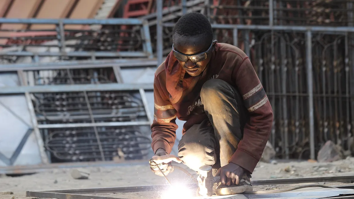

Hardbanding a tool joint requires a controlled thermal cycle: preheat the joint to a measured 400 to 600 °F (204 to 316 °C) depending on the steel’s carbon equivalent and the alloy system, hold interpass temperature inside a controlled band, lay the beads in a symmetric spiral or offset stringer pattern on the outer third of the joint, and cool the joint slowly in still air or insulation. The details below give a parameter framework adaptable to a specific alloy, machine, and pipe spec. Nothing here replaces the alloy manufacturer’s procedure data sheet or an applicable API, IADC, or operator specification, but it gives the structure most of those documents assume the welder already knows.
Why does the thermal cycle matter more than the welding machine?#
Hardbanding is a thermal-cycle problem, not an arc-parameter problem, because hardbanding is not a structural weld. The deposit carries no load, and the joint itself does not need to be restored to its original strength. Two failure modes are being managed: hydrogen cracking in the heat-affected zone (HAZ) of the quenched-and-tempered tool joint steel, and cracking or spalling of the deposit itself from excessive cooling stress.
A perfect bead placed on an improperly preheated 4145H joint will crack in the HAZ two inches behind the weld as it cools. A poorly tuned arc on a correctly preheated joint that cools slowly will usually hold. That is why this procedure allocates more attention to preheat, interpass control, and cool-down than to wire feed speed.
For background on how the deposit alloys themselves resist wear, see How Hardband Alloys Resist Abrasion Downhole. If you are weighing crack-prone tungsten carbide systems against crack-free chromium-carbide or complex-alloy wires, the preheat and cooling rules below change slightly, and the comparison in Tungsten Carbide vs Chromium Carbide Hardbanding covers the metallurgy behind those differences.
What preheat temperature should a tool joint receive?#
Preheat for tool joints is driven by the carbon equivalent (CE) of the base steel, the thickness and geometry of the joint, and the hydrogen sensitivity of the consumable. The common tool joint steels (4137M, 4145H, and non-magnetic austenitic grades in some directional programs) fall into these practical bands:
| Joint material / condition | Typical preheat range (°F) | Typical preheat range (°C) | Notes |
|---|---|---|---|
| 4137M tool joints, standard Q&T | 400 to 500 | 204 to 260 | Most rotary-shouldered connections |
| 4145H high-strength joints | 500 to 600 | 260 to 316 | Higher CE, higher crack sensitivity |
| Cracked-on-purpose carbide deposits | Top end of the steel’s range | Top end of the steel’s range | The deposit is expected to check-crack; keep the HZ sound |
| Crack-free alloy deposits | Follow the alloy data sheet; often 350 to 550 | Follow the alloy data sheet | Some crack-free alloys are less tolerant of over-preheat than of under-preheat |
| Non-magnetic austenitic joints | Lower preheat, higher interpass floor | Lower preheat, higher interpass floor | Austenitics do not harden on cooling, but avoid sensitization ranges |
What rules of thumb guide preheat without a mill cert?#
Two rules of thumb help when you do not have a mill cert in hand:
- When in doubt, run the hotter end of the range. Under-preheat causes HAZ hydrogen cracking, which is the most expensive failure in hardbanding. Slight over-preheat mostly costs fuel and operator discomfort.
- Preheat a wider band than you will weld. Heat at least 1 to 2 inches (25 to 50 mm) beyond each side of the deposit zone, plus the full width of the pattern. A cold ring around a hot weld zone is a crack initiator.
How should preheat be applied and verified?#
Preheat verification should be done at the metal surface, not at the heat source, using induction coils, oxy-fuel ring burners, or resistance heating blankets. All of these methods work; what matters is even heating around the full circumference:
- Measure with a contact pyrometer, temperature-indicating crayons or sticks, or a calibrated IR gun with emissivity set correctly for oxidized steel. IR guns on shiny or freshly machined surfaces read low, which is a common cause of “we preheated to 500 but it cracked anyway.”
- Verify temperature at the weld line, on the shoulder-side edge of the pattern, and at the far edge. If the spread across the pattern area exceeds roughly 75 °F (40 °C), heat longer rather than hotter.
- Once the joint reaches temperature, let it soak. A common guideline is to bring the full wall to temperature and give it a short dwell (several minutes for a tool joint cross-section) so the bore side of the wall is not still cool.
- Remove surface oxides and soot from the weld zone just before welding if you heated with oxy-fuel. Scale and carbon smut cause porosity and poor fusion.
What deposition parameters are used for GMAW hardbanding?#
Hardbanding is almost universally done with a welding lathe or positioner rotating the pipe under a GMAW (or flux-cored) torch. Typical parameters, to be treated as a starting frame and tuned against the alloy data sheet:
| Parameter | Typical starting range | What changes it |
|---|---|---|
| Wire diameter | 0.045 to 1/16 in (1.1 to 1.6 mm) | Alloy availability, machine power, bead size wanted |
| Wire feed speed | 250 to 450 in/min | Deposit rate needed, arc characteristics of the alloy |
| Voltage | 24 to 32 V | Alloy’s transfer behavior; carbide-loaded wires tolerate less arc length |
| Amperage | 200 to 350 A | Follows from WFS and stick-out |
| CTWD / stick-out | 3/4 to 1-1/4 in (19 to 32 mm) | Longer stick-out reduces dilution in some setups |
| Travel (surface) speed | 20 to 60 in/min at the joint surface | Controls bead thickness, typically 1/16 to 1/8 in deposit |
| Shielding gas | 75/25 Ar/CO2 common; follow data sheet | Gas choice affects arc stability and deposit chemistry |
| Transfer mode | Short-arc or spray depending on wire and current | Many carbide systems prefer lower energy to limit carbide dissolution |
Why do dilution and arc energy dominate parameter selection?#
Two points deserve emphasis:


- Dilution is the enemy of wear life. Excessive heat input melts base metal into the deposit, diluting the carbide or boride content. Hardbanding deliberately uses low dilution practice: fast travel, controlled stick-out, and multiple thin passes rather than one thick pass.
- Carbide survival depends on arc energy. Tungsten carbide particles dissolve in an overly hot arc. If your alloy contains discrete carbides, favor the lower-voltage, faster-travel end of the ranges above and let bead overlap build thickness.
Which bead placement patterns are used in tool joint hardbanding?#
Two patterns dominate tool joint hardbanding: the continuous spiral and offset circumferential stringers. Pattern choice affects heat distribution, repairability, and bead geometry control.
- Continuous spiral. One continuous stringer wound around the rotating joint at a fixed pitch. This is the fastest to apply on a lathe, gives uniform heat distribution, and is the common choice for shop work.
- Offset circumferential stringers (rings). Individual rings placed side by side with a small gap or light overlap. Easier to control bead geometry, easier to repair a single ring later, and common on heavier builds and repair work.
What placement rules constrain the deposit location?#
Regardless of pattern, placement is constrained by connection geometry and inspection criteria:
- Axial position: the deposit goes on the outer third of the pin or box, with a standoff from the shoulder face, commonly on the order of 1/2 to 3/4 inch (13 to 19 mm), per the applicable spec. Deposits too close to the shoulder interfere with the sealing face and torque makeup.
- Width: typically two to five beads wide (roughly 3/4 to 1-1/2 inches), depending on operator or spec requirements. Wider is not better; a wider band raises heat input per joint and increases residual stress.
- Symmetry: the pattern must be symmetric around the circumference. A lopsided deposit creates imbalance and uneven wear against casing.
- Height: single-layer deposits typically target a specific as-welded height above the joint surface (often in the 1/16 to 3/32 in range, per spec) so the pipe still passes gauge and does not gouge casing on initial runs.
- Casing wear consideration: in directional or extended-reach wells, the pattern and alloy must suit the casing environment, which is covered in depth in Casing-Friendly vs Abrasive Hardband Alloys.
A practical sequencing note: if you are placing multiple rings, weld them in a staggered or alternating order rather than walking from one edge to the other. This keeps heat distribution even and avoids building a hot band on one side of the pattern.
How is interpass temperature controlled during hardbanding?#
Interpass temperature is the range the joint is allowed to be at when starting (and remaining at during) each subsequent bead, and for hardbanding the floor equals the preheat temperature. The joint should not cool below your selected preheat before or between beads. In practice, most procedures set an interpass band such as 400 °F minimum / 700 °F maximum (204 °C min / 371 °C max), adjusted for the steel.
The interpass ceiling matters too. Excessive interpass temperatures enlarge the HAZ, over-temper the base steel, and increase dilution. If the joint is running hot because of continuous welding, either increase rotation speed slightly (faster travel per revolution spreads the heat) or pause between rings.
Which field controls keep interpass temperature in band?#
Field controls that work:
- Use the same contact pyrometer or temp sticks used for preheat verification. Check between beads, at the bead start location, on at least two points around the circumference.
- On multi-bead patterns, check interpass at the leading edge of the pattern where you are about to weld, not on the bead just deposited.
- For shop lathes, use a dwell or a slow-index pass between beads if your controller supports it, rather than stopping rotation cold.
How should a hardbanding joint be cooled down?#
Cool-down is where good hardbanding procedures are won or lost: the deposit is at its most crack-sensitive right after the arc goes out, while the HAZ passes through the martensite-formation range. The joint should cool slowly and evenly from the interpass temperature down through the critical range (roughly 800 to 500 °C, or 1470 to 930 °F, on the surface of the weld region) and continue slowly to handling temperature.
Practical methods, in rough order of preference:
- Insulated still-air cooling: wrap the joint in a weld blanket or thermal wrap immediately after the last bead, and let it cool in still ambient air. This is the default for shop work.
- Oven or controlled cooling booth: transfer the joint to a furnace or cooling box held at a low setpoint (for example 500 to 600 °F) and ramp down gradually. Best for high-CE joints and heavy-wall sizes.
- Vermiculite or dry sand burial: a low-tech, effective method for field and small-shop work. Bury the joint while hot and leave it undisturbed until it reaches handling temperature.
What cool-down practices cause cracking?#
What not to do:
- Never quench, spray, fan, or cool with compressed air. This is the single most common cause of deposit and HAZ cracking in marginal work.
- Do not move, roll, or strike the joint while it is hot through the critical range. Thermal shock plus mechanical shock is a reliable crack recipe.
- Do not apply hardband to a joint that will sit in cold wind or on cold steel racks immediately after welding. If ambient conditions are cold, insulate more, and consider a higher preheat to compensate.
What temperature is safe for handling a hardbanded joint?#
A reasonable handling threshold is below roughly 250 to 300 °F (120 to 150 °C) before the joint is moved, stacked, or quenched by rain or snow exposure. Above that, the surface-to-core differential from handling and ambient shock can still drive cracks in heavy sections.
How does re-application change the hardbanding procedure?#
When re-applying hardband over an existing deposit, the thermal procedure changes because the old deposit’s condition dictates whether to remove it entirely, dress it, or weld over it. Preheat rules generally stay the same or get slightly more conservative, because the existing deposit’s hardness and the interface condition add uncertainty. The decision framework and removal methods are covered in Re-Applying Hardband Over Existing Deposits.
One habit that pays: document preheat, interpass, and cool-down method for every joint. If a deposit fails in the field, the thermal record is the first thing anyone asks for. If you run crack-intentional alloys, see Crack-Free Hardband Alloys: What Actually Works for how acceptance criteria differ between systems. For what inspectors will actually look for on the finished joint, Hardbanding Inspection and Acceptance Criteria outlines the rejection thresholds.
Key takeaways#
- Preheat 400 to 600 °F for standard Q&T tool joint steels; verify at the metal surface, never at the heat source.
- Hold interpass within a controlled band, with the floor equal to preheat and a ceiling high enough to avoid over-tempering the joint.
- Use low-dilution practice: thin beads, fast surface travel, controlled arc energy, especially with carbide-bearing wires.
- Place the pattern symmetrically on the outer third of the joint, respecting shoulder standoff, width, and height limits.
- Cool slowly and deliberately, wrapped or buried, with no quenching or cold-air exposure until the joint is below roughly 300 °F.
- Record the thermal cycle for every joint; the preheat and cool-down record is the first document anyone reviews after a field failure.
- Hardbanding
- Gas metal arc welding
- Tool joint
- Heat-affected zone
- Carbon equivalent
- Tungsten carbide
- Chromium carbide
- 4145H steel